🔍

  • 1.Determine the permeability of magnetic material by plotting its BH curve
  • 2. Measure voltage, current and power in 1-phase circuit with resistive load.
  • 3. Measure voltage, current and power in R-L series circuit.
  • 4.Determine the transformation ratio (K) of 1-phase transformer.
  • 5.Connect single phase transformer and measure input and output quantities.
  • 6.Make Star and Delta connection in induction motor starters and measure the line and phase values.
0 like 0 dislike

6 Answers

Practical no. 1

Aim: Determine the permeability of magnetic material by plotting its BH curve

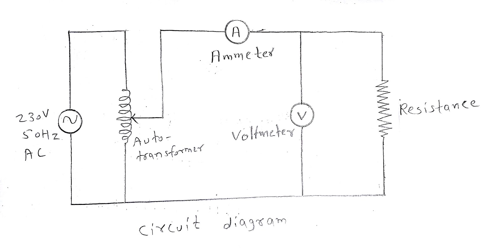
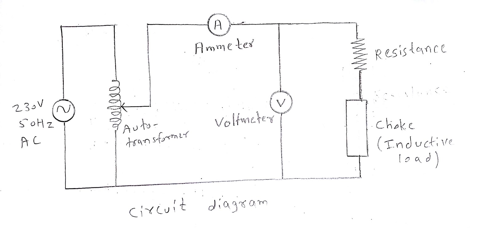
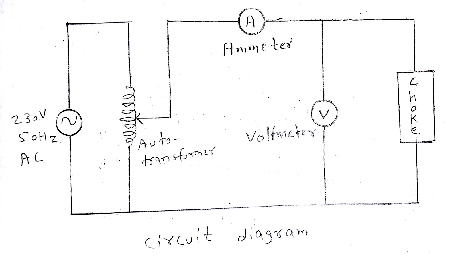
Apparatus required:  voltmeter, ammeter, choke, autotransformer
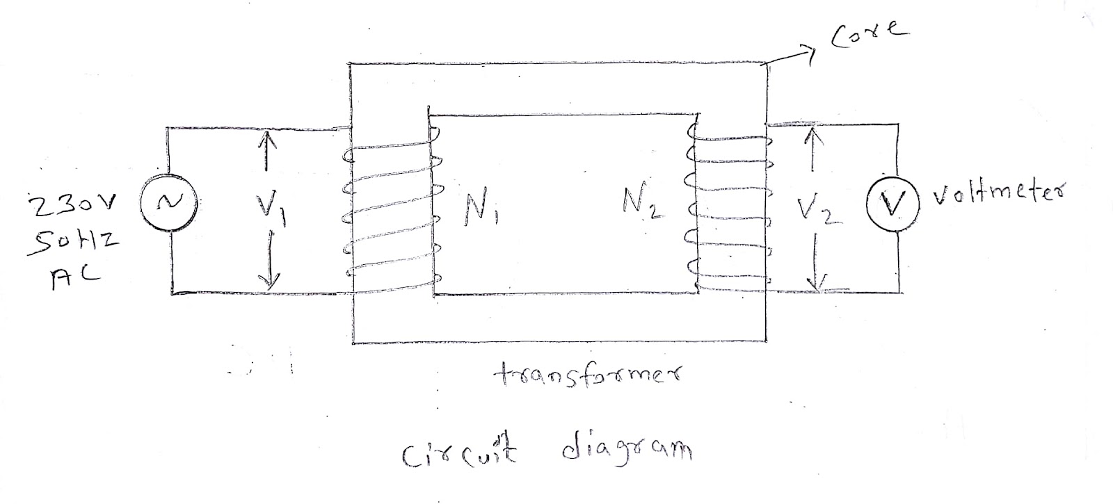
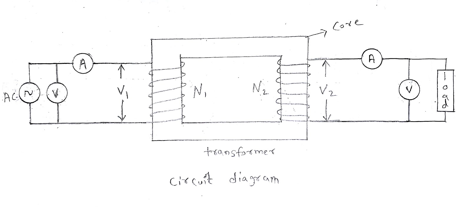
Circuit diagram:

imageimage

image


Theory:

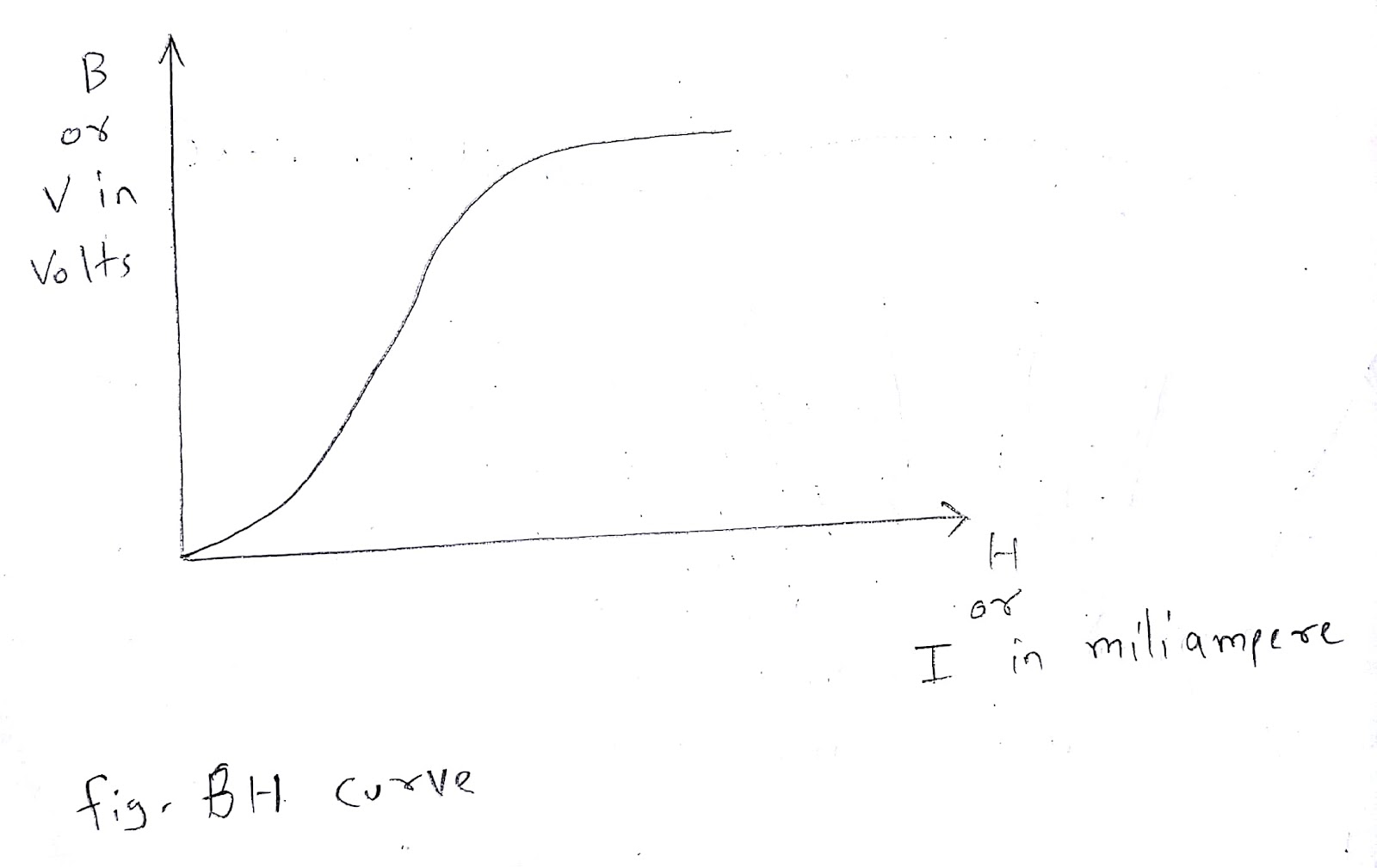
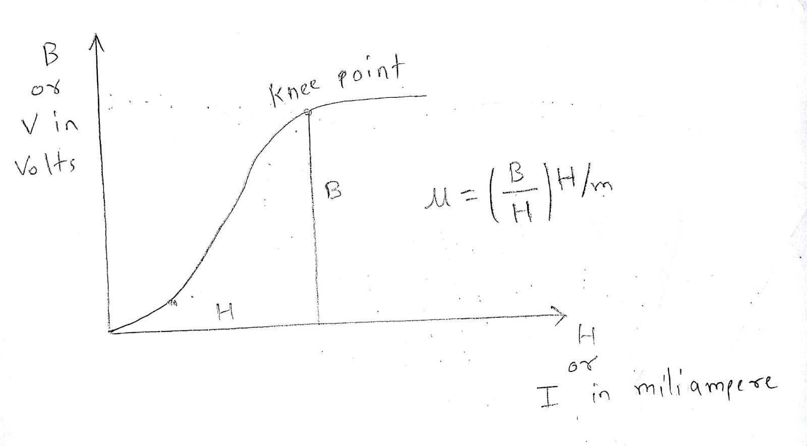
BH curve is the graph plotted between B (i.e. flux density) and H (i.e. magnetic field strength). H is taken on x-axis and B is taken on y-axis. Different magnetic materials have different BH curve. And non magnetic material have a straight line instead of curve.

Initially the B and H increases slowly but after instep B increases rapidly. And after knee point the B start getting saturated. And at Bmax there is a straight line called saturation. After Bmax the B will not increase further. BH curve is also called as magnetization curve.

Permeability (μ) is the ratio of B and H.


Procedure:

  1. Connect the equipments as shown in circuit diagram.

  2. Before turning on supply check whether the connection is correct or not.

  3. Keep the autotransformer on zero volt and turn on the mains.

  4. Slowly increase the voltage of autotransformer.

  5. Take the reading of current on ammeter and voltage on voltmeter.

  6. Draw the graph from current and voltage readings.

  7. Calculate the permeability from BH curve.


Precautions:

  1. Make the connections tight.

  2. Do not connect wrong wiring.

  3. Check the connection before turning on mains supply.

  4. Do not touch any conducting part when the supply is on.

  5. Avoid short circuit of connecting wires.


Result: Hence we have performed the practical and permeability of magnetic material is ________ H/m.

0 like 0 dislike

Practical no. 2

Aim: Measure voltage, current and power in 1-phase circuit with resistive load.


Apparatus required:  voltmeter, ammeter, resistance, autotransformer


Circuit diagram:

image


Theory:

The single phase AC required two wires one is for line and second is for neutral. AC have changing magnitude and direction. AC have some limited frequency. In India the frequency used is 50 Hz. When we connect the resistive load the voltage and current give unity power factor. We can measure the current by connecting ammeter in series and voltage by connecting voltmeter in parallel. By multiplying the value of voltage and current we can obtained the value of power.


Procedure:

  1. Connect the equipments as shown in circuit diagram.

  2. Check the connection and turn on the switch.

  3. Take a reading of current on ammeter and voltage on voltmeter.

  4. Calculate power by multiplying voltage and current.


Precautions:

  1. Make the connections tight.

  2. Do not connect wrong wiring.

  3. Check the connection before turning on mains supply.

  4. Do not touch any conducting part when the supply is on.

  5. Avoid short circuit of connecting wires.


Result: Hence we have measured the voltage, current and power in 1-phase circuit with resistive load.

0 like 0 dislike

Practical no. 3

Aim: Measure voltage, current and power in R-L series circuit.


Apparatus required:  voltmeter, ammeter, resistance, inductive load (choke),  autotransformer


Circuit diagram:

image


Theory:

The 1-phase AC is use in our homes which is 230 volts and 50 Hz. Many of our home loads are inductive like fan, washing machine etc.. When the inductive load is there current lags the voltage.


Procedure:

  1. Connect the equipments as shown in circuit diagram.

  2. Check the connection and turn on the switch.

  3. Take a reading of current on ammeter and voltage on voltmeter.

  4. Calculate power by multiplying voltage and current.


Precautions:

  1. Make the connections tight.

  2. Do not connect wrong wiring.

  3. Check the connection before turning on mains supply.

  4. Do not touch any conducting part when the supply is on.

  5. Avoid short circuit of connecting wires.


Result: Hence we have measured the voltage, current and power in 1-phase circuit with R-L load.

0 like 0 dislike

Practical no. 4

Aim: Determine the transformation ratio (K) of 1-phase transformer.


Apparatus required:  voltmeter, transformer


Circuit diagram:

image


Theory:

There are two windings in Transformer one is called primary winding and second is called secondary winding. Primary winding have N1 number of turns and secondary winding have N2 number of turns.


The ratio of secondary number of turns N2 and primary number of turns N1 is called as transformation ratio. Transformation ratio is denoted by K.


Mathematically transformation ratio is given by,


Transformation ratio (K) = N2/N1 = V2/V1


Procedure:

  1. Connect the equipments as shown in circuit diagram.

  2. Check the connection and turn on the switch.

  3. Take a reading of voltage on voltmeter for both input and output.

  4. Calculate the transformation ratio from V2 and V1.


Precautions:

  1. Make the connections tight.

  2. Do not connect wrong wiring.

  3. Check the connection before turning on mains supply.

  4. Do not touch any conducting part when the supply is on.

  5. Avoid short circuit of connecting wires.


Result: Hence we have determined the transformation ratio (K) of 1-phase transformer.

0 like 0 dislike

Practical no. 5

Aim: Connect single phase transformer and measure input and output quantities.


Apparatus required:  voltmeter, ammeter, transformer


Circuit diagram:

image


Theory:

The transformer is a static device which transforms electrical power by stepping up AC voltage and stepping down AC current or by stepping down AC voltage and stepping up AC current and keeping frequency constant.

There are two coils in transformer. one is called primary winding and second is called secondary winding. These two winding are inductively linked. The Transformer works on the principle of mutual induction. The principal of mutual induction states that if the current in one coil is changing this changing current will produce changing magnetic flux and this changing magnetic flux will produce EMF in in second coil. The EMF is called statically induced EMF.


Procedure:

  1. Connect the equipments as shown in circuit diagram.

  2. Check the connection and turn on the switch.

  3. Take a reading of current on ammeter and voltage on voltmeter for both input and output.

  4. Calculate the input and output quantities.


Precautions:

  1. Make the connections tight.

  2. Do not connect wrong wiring.

  3. Check the connection before turning on mains supply.

  4. Do not touch any conducting part when the supply is on.

  5. Avoid short circuit of connecting wires.


Result: Hence we have measured the input and output quantities of transformer.

0 like 0 dislike

Practical no. 6

Aim: Make Star and Delta connection in induction motor starters and measure the line and phase values.


Apparatus required:  voltmeter, ammeter, induction motor


Circuit diagram:

image

image


Theory:

In case of induction motor starting heavy current flows but by connecting the stator coils in star connection we can reduce the starting current and when the induction motor is in running condition we can connect the stator coils in delta connection.

In case of star Line voltage (VL) = √3 Phase voltage (Vph) and Line current (IL) = Phase current (IPH). In case of delta Line voltage (VL) = Phase voltage (Vph) and Line current (IL) = √3 Phase current (IPH).


Procedure:

  1. Connect the equipment and wiring properly.

  2. Measure current using ammeter and voltage using voltmeter.


Precautions:

  1. Make the connections tight.

  2. Do not connect wrong wiring.

  3. Check the connection before turning on mains supply.

  4. Do not touch any conducting part when the supply is on.

  5. Avoid short circuit of connecting wires.


Result: Hence we have measured the line and phase value of star and delta connection.

0 like 0 dislike

Related questions

What is the meaning of Electronics and Communication Engineering?

View solution
0 like 0 dislike
0 answers

Electrical quantities (symbol and basic unit)
Answer : Electrical quantities (symbol and basic unit) ...

View solution
0 like 0 dislike
1 answer

GATE 2020 syllabus electrical engineering
Answer : EE: Electrical Engineering Section 1: Engineering Mathematics Linear Algebra: Matrix Algebra, Systems of linear equations, Eigenvalues, Eigenvectors. Calculus: Mean value theorems, Theorems of ... to dc converters, Single phase and three phase inverters, Sinusoidal pulse width modulation. ...

View solution
0 like 0 dislike
1 answer

Write short notes on fire extinguishing methods adopted in electrical engineering. 
Answer : Stand 6 to 8 feet away from the fire and follow the four-step PASS procedure. If the fire does not begin to go out immediately, leave the area at once. Always be sure ... fire causing the particles to expand chemically inhibiting combustion and expelling the oxygen thereby smothering the flames. ...

View solution
0 like 0 dislike
3 answers

Electrical engineering
Answer : https://youtu.be/ZKnK7Na2Frw...

View solution
0 like 0 dislike
1 answer

50.5k questions

47.1k answers

240 comments

7.0k users